
Case Study 1 – Gear Mechanism for a Galvanizing Line
Initial Situation and Task Definition
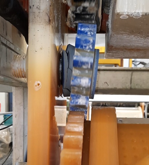
In a galvanizing line from the 1950s–60s, where original spare parts no longer exist, the gear mechanism experiences rapid wear. This mechanism is based on sliding friction between a plastic bushing and hub. The main materials used are polypropylene and Teflon, since the mechanism is immersed in a chemical bath and metal parts cannot be used. Currently, this mechanism is outsourced abroad as a non-original spare part, with a lifespan of only a few weeks. The goal is to replace the original mechanism with an innovative solution with a longer lifespan.
Development and Prototyping
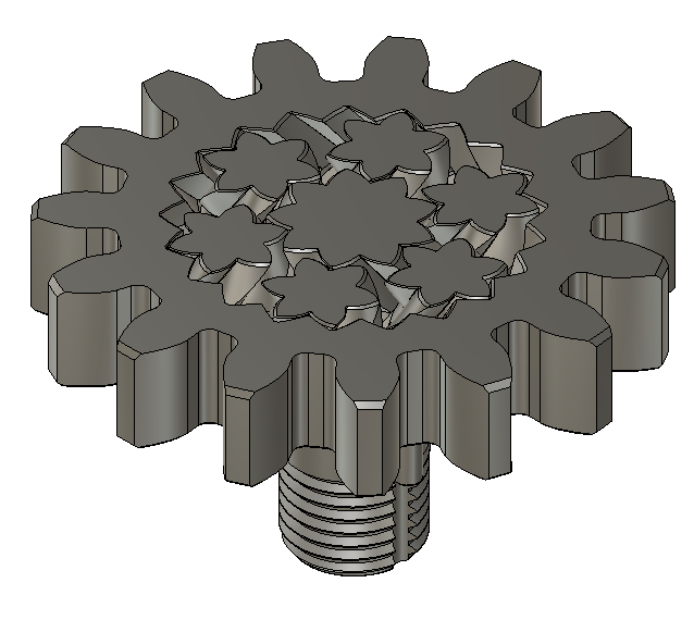
During development, the aim was to replace sliding friction, which produces high temperatures and reduces the mechanism’s lifespan, with rolling friction. However, bearings with steel balls and cages also cannot be used. Therefore, our innovative solution integrates the gear mechanism directly into the assembly, which is produced as a single, inseparable plastic part using 3D printing. This unique mechanism can only be manufactured with additive technologies and solves the core problem—low lifespan and high friction. After producing a prototype set, we optimized the clearances and tolerances of the mechanism and manufactured various samples from several materials for final operational testing.
Introduction to Small-Batch Production
Testing is still ongoing, as this is a long-term process for measuring lifespan and reliability. However, after final confirmation, we are able to supply over 50 mechanisms within 5 working days, covering the expected annual consumption, including spares. Moreover, we can produce without any quantity limitations—even single units, and express delivery within 24 hours if needed, since this is a key component of the entire galvanizing line.
Case Study Evaluation
By utilizing the possibilities of additive design with minimal manufacturing constraints, we developed an innovative solution for a critical gear mechanism part. 3D printing made it possible to produce prototypes as well as economically and quickly cover the needs of small-batch production without the need for any additional technologies or tools.
Case Study 2 – Custom Production Jigs
Initial Situation and Task Definition
The task was to develop, verify the functionality, and produce a small series of bending jigs for aluminum tubes that would be compact and lightweight.
The huge potential of 3D printing, which is still only partially utilized, lies in manufacturing jigs—whether machining, clamping, measuring, etc. With the development of new materials that are extremely rigid and strong, this area is quickly moving into practical use in manufacturing companies. These are mainly composite materials with carbon or glass fiber additives. These provide the necessary rigidity and dimensional stability.
Geometry Preparation
Based on the requirements, we had clear information about the basic dimensions of the jig. Through step-by-step modeling in a CAD system, we first created the functional surfaces and then connected them into a single unit, making it lighter and manufacturable with the selected technology.
Prototyping and Small-Batch Production
Since the model was optimized for the chosen 3D printing technology, the prototype was completed within 12 hours. The jig passed the tube bending test, and after customer approval, we produced additional units.
Case Study Evaluation
We took advantage of additive manufacturing already at the design stage, which allowed us to reduce production costs and delivery times. By optimizing the model for technology, we met the requirements for the jig—compactness and low weight.
For significantly higher strength, reinforcement is used on special dual-head 3D printers, where, in addition to reinforced filament, the body is reinforced in certain layers with continuous carbon, glass, or Kevlar fibers.
These can increase the strength and rigidity of the part by up to 20 times. A product reinforced with continuous carbon fibers can achieve a tensile strength of up to 800 MPa, with a flexural strength of 540 MPa. Compared to aluminum 6061, these products have a 50% higher flexural strength-to-weight ratio and up to 3 times higher tensile strength.
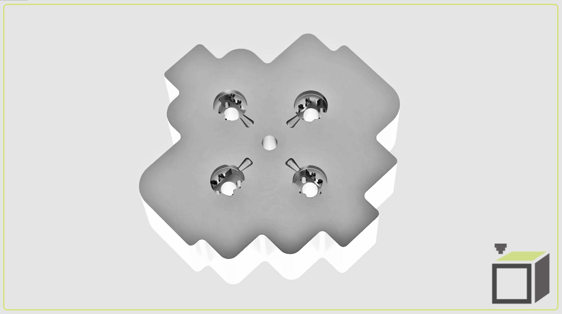
Case Study 3 – Improving Injection Mold Cooling
Initial Situation and Task Definition
The task was to design the geometry of internal cooling channels for an existing injection mold to increase injection quality and especially the productivity of the production process in high-volume series.
Development
Conventional manufacturing of mold cooling channels involves drilling straight channels and sealing them, which fundamentally does not allow for uniform cooling in complex, multi-cavity molds.
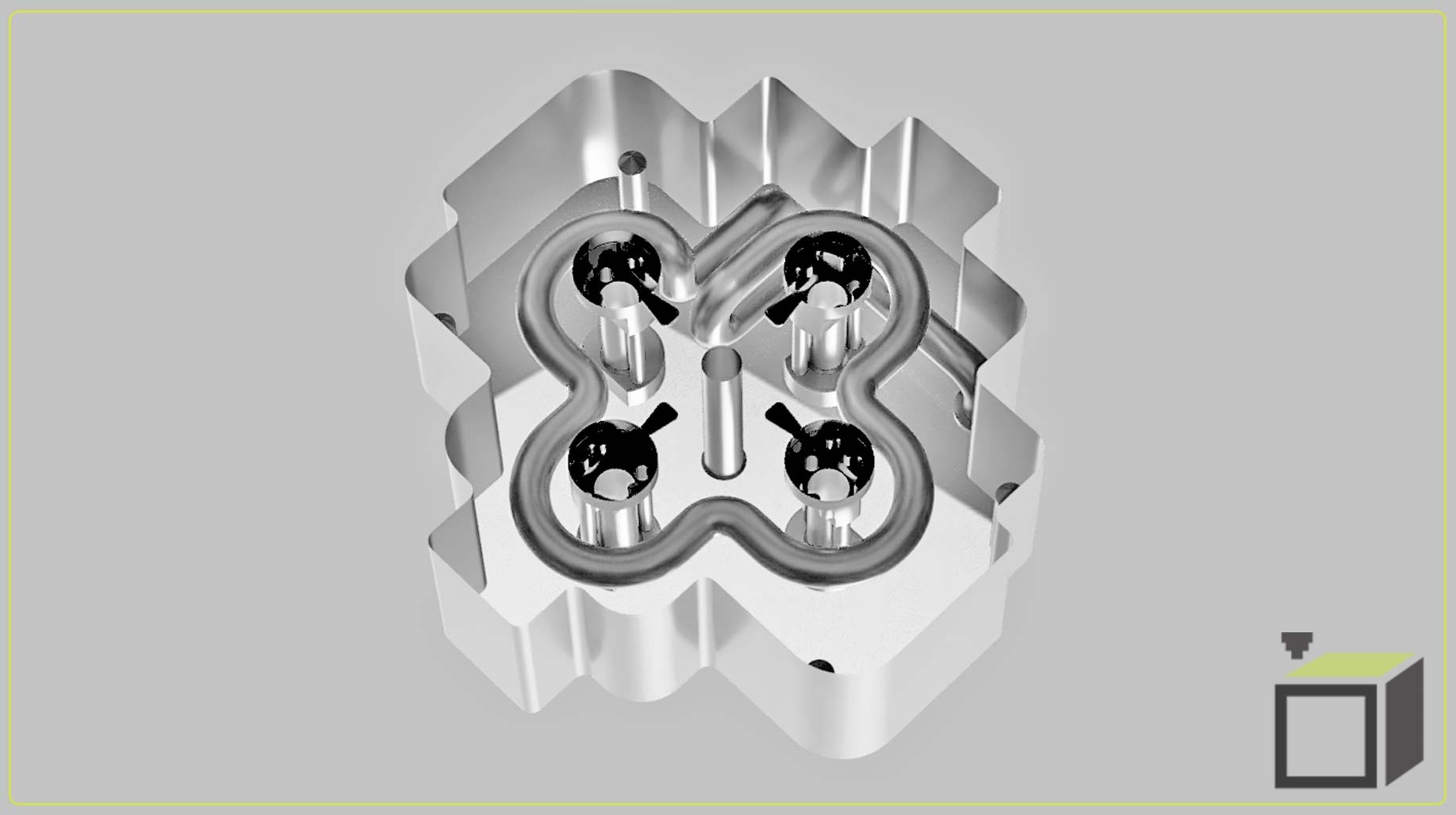
Therefore, we chose additive manufacturing of metal by 3D printing using SLM/DMLS technology (laser sintering of tool steel), which gives us much more freedom in design and production, allowing us to design any cross-section and shape of cooling channels.
Case Study Evaluation
Given the lower precision of additive technologies (tenths of a millimeter), we designed the mold with allowances for conventional machining of functional surfaces. The only added value of additive manufacturing in this project was the internal geometry, which cannot be produced by any other means. The mold insert blank was made of tool steel and hardened to 52–54 HRC.
By optimizing the position of these channels, we achieved increased production efficiency and overall improvement of the injection molding process.
Case Study 4 – Development and Production of Flame-Retardant Electronic Enclosures
Initial Situation and Task Definition
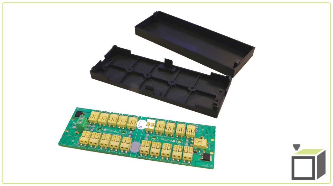
The task was to design, prototype, and subsequently produce a series of electronic enclosures according to the supplied PCB. The project required the use of a certified material meeting UL 94-V0, which specifies the level of flame retardancy.
Geometry Preparation and Prototyping
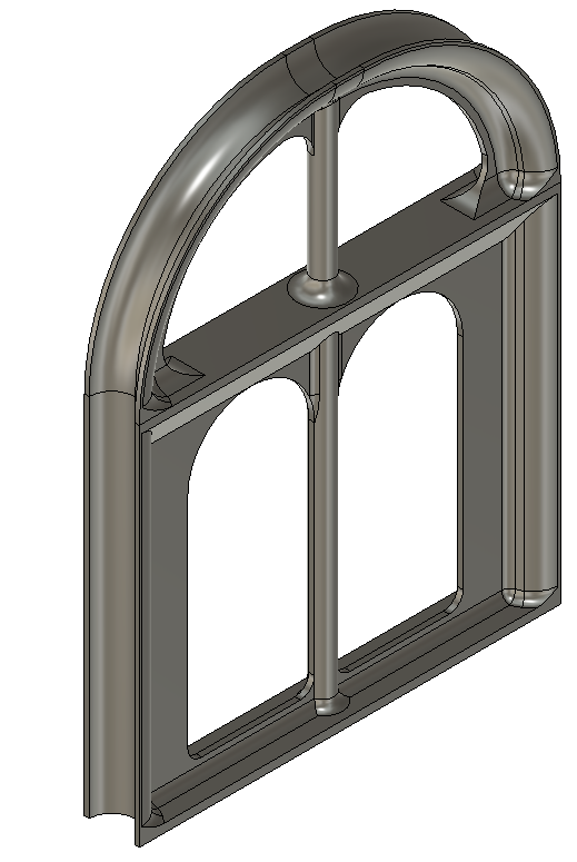
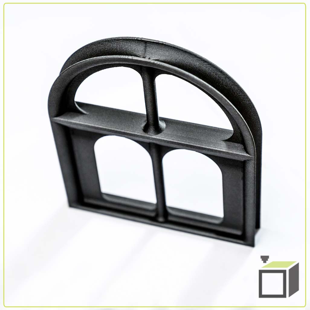
Several design variations were prepared and presented to the client as visualizations for feedback before production. After selecting the appropriate variant, we incorporated technological features for the chosen FDM 3D printing technology and produced a prototype.
The product has external dimensions (L x W x H) 145 x 54 x 28 mm.
The design was conceived so that built-in snaps fit into the counterpart’s slots, securely holding both parts of the enclosure, while also allowing easy disassembly. The PCB was mounted using 4 screws and holes in the board.

Case Study Evaluation
The result is a functional part certified for UL 94-V0, lightweight, and production is flexible and adapted to current demand—without the need for molds or stocking large quantities.
Case Study 5 – Reverse Engineering and Production of a Wax Model
Initial Situation and Task Definition
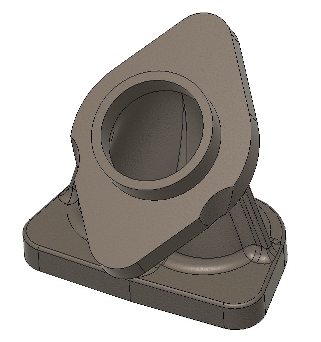
The client had a physical part from which additional replicas were needed. It was a shaped flange with no technical documentation or 3D models. The goal was to create a positive mold from wax for casting and subsequent machining of holes and critical surfaces.
Reverse Engineering
Due to the complex geometry, we started with 3D scanning to accurately capture the shapes. We then continued with reverse engineering using parametric modeling in a CAD system to achieve the required shape with clearly defined surfaces and dimensions. Technological features and allowances were incorporated into the part.
Prototyping and Small-Batch Production
After modeling was complete, we began detailed production using castable wax material, specifically designed for mold making, as it can be easily melted out at about 270°C with almost zero ash residue. After successful prototype testing, we produced several more units for further mold production.… 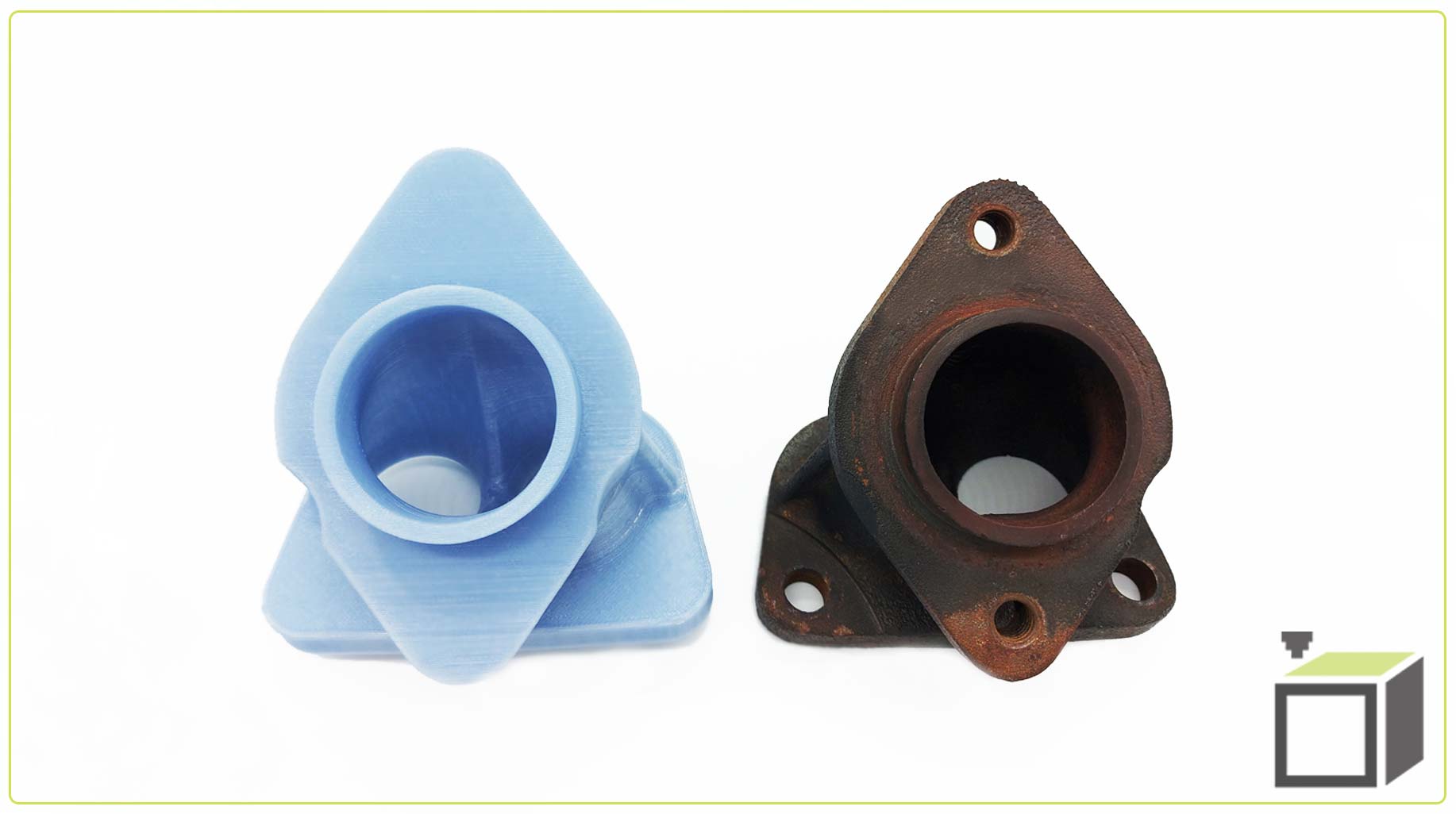
Case Study Evaluation
Using reverse engineering tools, we prepared the necessary 3D model for wax model production. The advantage is that the whole process is relatively fast and does not require complex tools or machinery. We completed the entire project within 4 working days from receiving the original sample to delivering the required number of wax models, achieving significant cost savings compared to full machining of the part.
If you are not sure whether we can help you, do not hesitate to contact us—we will be happy to advise you free of charge.
Read more news
Articles from the world of 3D printing
Manufacturability assessment
Manufacturability assessment and quotation begin upon receiving a 3D model in STEP, STP, STL, OBJ, or 3MF format. If you don’t have your own 3D model, we can help create one based on your specifications by sending us a photo, drawing, or sketch.
Are you interested in our offer? Contact us.
Please submit your inquiries directly via the non-binding inquiry form.
We will be better able to prepare an offer for you based on your specific requirements.